HopeRF RFM95, Teensy and Multitech LoRa Conduit working together.
In order to test HopeRF radio, I decided to use the existing code running on Teensy MCU (v: 3.2) in public LoRa mode.
You will need the following:
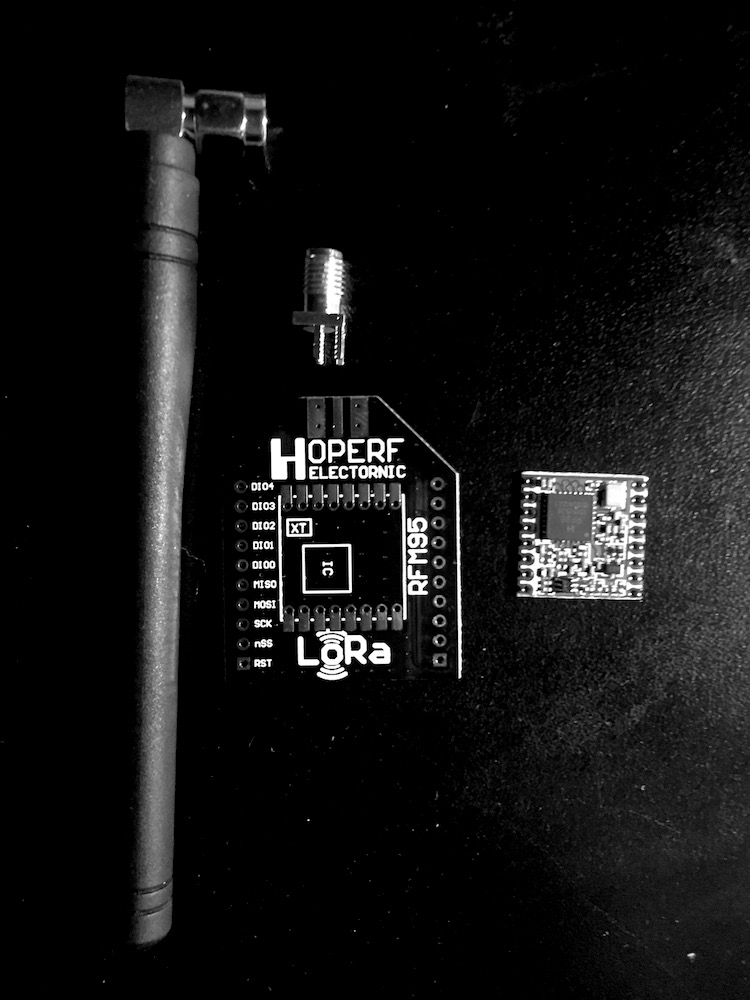
- hopeRF95 radio module


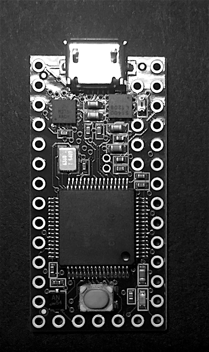
- teensy 3.1/3.2 MCU board
- hopeRF adapter with SMI antenna connector (optional)
- hopeRF antenna (optional, instead you can just use 8.2cm wire)
Keep in mind that my goal here is to focus on HopeRF’s radio testing as Teensy MCU is way too expensive and consumes too much power to even be consider it for production usage.
To start, you will need to solder few wires together:
Teensy LC/3.1/3.2 — RFM92/95
GND — GND
3.3V — 3.3V
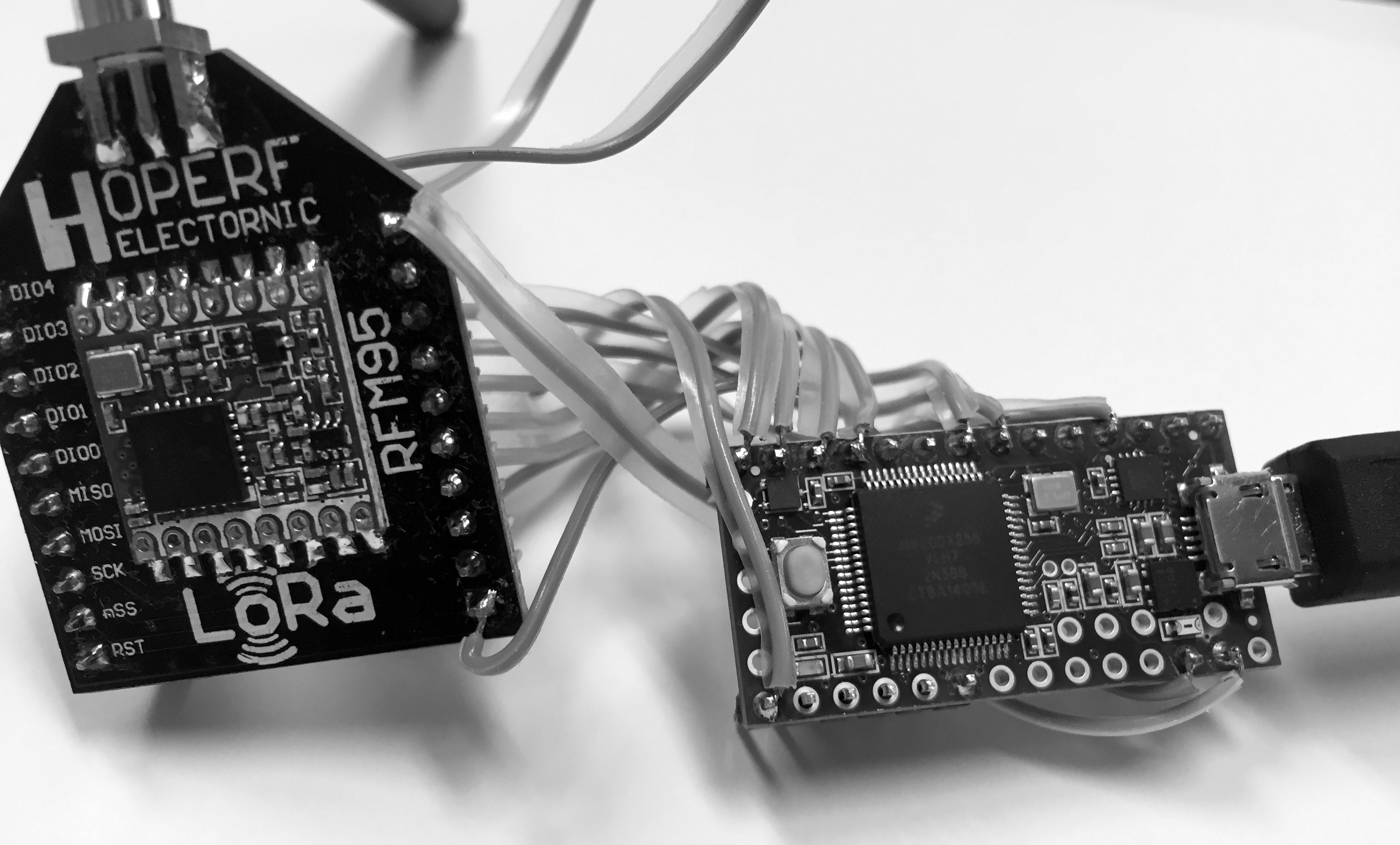
RFM95 & Teensy
2 — DIO0
5 — DIO1
6 — DIO2
9 — RESET
10 — NSS
11 — MOSI
12 — MISO
13 — SCK
Since Teensy is basically yet another Arduino Development Platform, we will use Arduino SDK with Teensyduino add-on to program Teensy with IBM’s LoraMac.
You can just follow this set of instructions to get Teensyduino running on your platform.
Once installed, try compiling one of the demo programs for Teensy, just to make sure that everything went ok.
Now, we are ready to proceed with actual LoRaMac code. First, Clone the whole package to your system, then add it as new library to your Arduino SDK.

You are almost done ;), just few modifications left…
I will be using defaults with the exception of the DevAddr below.
In the main file, we need to change DevAddr to something unique globally.
static const u4_t DEVADDR = 0x03FF0001 ;
//In this example I used 0x03FFEBB2, you will see it below in the section when we define node manually in gateway's db.
This is equivalent of MAC address associated with your Ethernet port. In production, you will have your own prefix, obtained from IEEE, but for now we can just use anything, as long as it’s not duplicated on your network.
Then, we will adjust Spreading Factor from 11 to 9 to match gateway configuration (as per FCC in North America, Spreading Factor could be between 7 and 10).
// Set data rate and transmit power (note: txpow seems to be ignored by the library)

LMIC_setDrTxpow(DR_SF9,14);
Now, you need to use your favoured editor to change the config.h located under arduino libraries (in case of MacOS: /Users/<Your User Name>/Documents/Arduino/libraries/arduino-lmic-v1.5-master/src/lmic to support 915MHz as North American ISM frequency and SX1276 chip for RFM95 HopeRF radio module.
#ifndef _lmic_config_h_

#define _lmic_config_h_
// In the original LMIC code, these config values were defined on the
// gcc commandline. Since Arduino does not allow easily modifying the
// compiler commandline, use this file instead. (MK)
//#define CFG_eu868 1
#define CFG_us915 1
//#define CFG_sx1272_radio 1
#define CFG_sx1276_radio 1
// 50 μs per tick
#define US_PER_OSTICK 50
#define OSTICKS_PER_SEC (1000000 / US_PER_OSTICK)
#endif // _lmic_config_h_
You can connect your Teensy, compile your code and program your board.
Go back to your gateway and manually add the node:
# nc -u localhost 6677

node add 03FFEBB2 0200000000EEFFC0 4242456789ABCDEF 2B7E151628AED2A6ABF7158809CF4F3C 2B7E151628AED2A6ABF7158809CF4F3C
Using the following syntax: node add [DevAddr] [APPEUI] [DEVEUI] [NwkSKey] [AppSKey]
Depending if you run gateway or packet forwarder, go to you logs or run mosquitto_sub -t lora/+/up to see incoming packets.
As soon as you run your demo code, you should see something like that:
{"chan":7,"cls":0,"codr":"4/5","data":"d29ybGQ=","datr":"SF9BW125","freq":"913.3","lsnr":"-12.8","modu":"LORA","rfch":1,"rssi":-113,"seqn":5,"size":8,"timestamp":"2015-11-18T16:08:51Z","tmst":2397020652}
where “d29ybGQ=” is base64 representation of the word “hi”.
Almost forgot about last cosmetic modification… in order to avoid an extra character at the end of the string, modify
// Prepare upstream data transmission at the next possible time.

LMIC_setTxData2(1, mydata, sizeof(mydata), 0);
to // Prepare upstream data transmission at the next possible time.
LMIC_setTxData2(1, mydata, sizeof(my data)-1, 0);
Enjoy and stay tuned…
Soon, I will share my experience with modules from one of the new LoRa node makers from China.
I will also experiment with LoRa range, explaining ways to get the most from your node…
Stay tuned…

 gateways from

